Hardware - SVBox IoT 1.0
Mounting the SmartVanBox Onboard
Once the SmartVanBox is ready, it can be placed inside the vehicle and secured with the appropriate screws.
We recommend positioning the SmartVanBox in an accessible location to facilitate the use of buttons, but also near the rest of the electrical system.
At this point, we can move on to the wiring.
Short Steps
- Position the SmartVanBox in an accessible and strategic location.
- Connect the power supply line to the service battery fuse box.
- Connect the SolarCharger using a USB2Serial cable.
- For 12V services:
- If using a Mosfet Relay Module, connect the 12V line to the SmartVanBox and configure the load connections.
- If using a Relay Module, connect the loads following the outlined steps.
Power Supply
To connect the SmartVanBox to the power supply, use a line (12V max. 3A) connected to the service battery fuse box, just like other electrical devices in the camper.
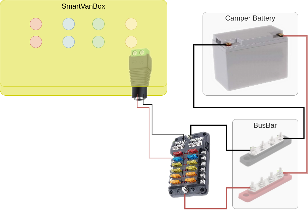
Connecting SmartVanBox to Power Supply with Pre-existing Electrical System a. Connecting the SmartVanBox Power Supply
SolarCharger USB2Serial
If you decide to integrate the solar charger using a USB2Serial cable, connect the USB side to the SmartVanBox and the pin side to the communication port of your solar charger.
 a. USB to Serial connection | 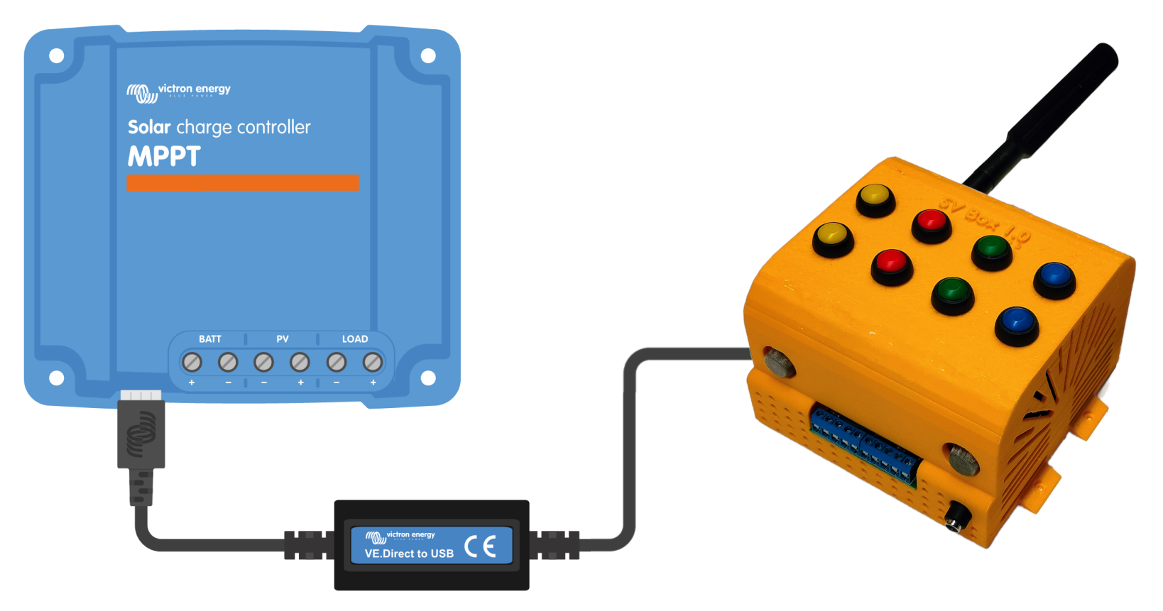 b. Victron to SmartVanBox |  c. Renogy to SmartVanBox |
12V Services
a. Mosfet module
If you have installed the Mosfet Relay module (default), connect a 12V line to the first two pins (starting from the right) of the SmartVanBox (1). This line can come directly from the busbar connected to the service battery or from the fuse box. In the latter case, use a suitable fuse to support all four loads you intend to connect to the SmartVanBox.
The remaining 8 pins form the 4 pairs of positive/negative cables to power your loads such as lights, motors, fans, etc. For safety, we recommend adding a fuse for each positive line towards the loads. You can use inline fuse holders like these; be mindful of the size of the provided cables.
a. Mosfet Relay Module PINOUT b. Load Connection Diagram
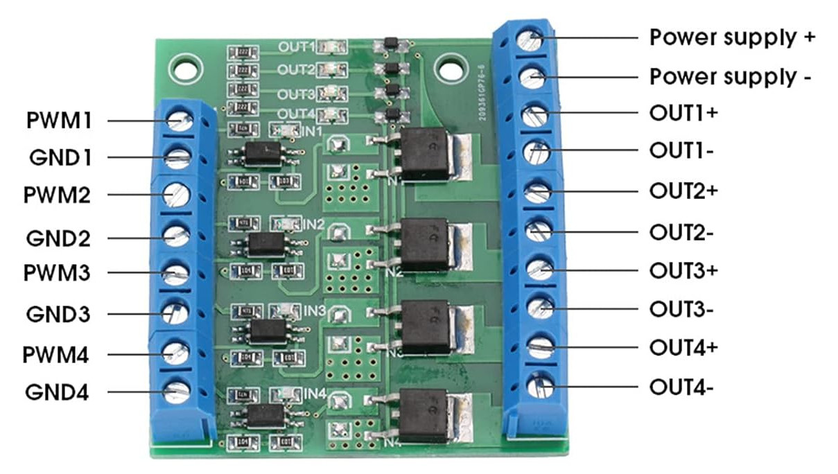 a. Mosfet Relay Module PINOUT | 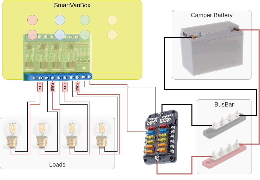 b. Load Connection Diagram for Mosfet Relay Module |
b. Relay Module
If you have installed a Relay Module instead, connecting the loads becomes easier. For each load to be connected to the SmartVanBox, bring a negative line from the busbar connected to the service battery to the available COM pins. Then, connect the negative load line to the corresponding NO (Normally Open) pin.
The positive load line can be connected to an output of the fuse box or directly to the busbar.
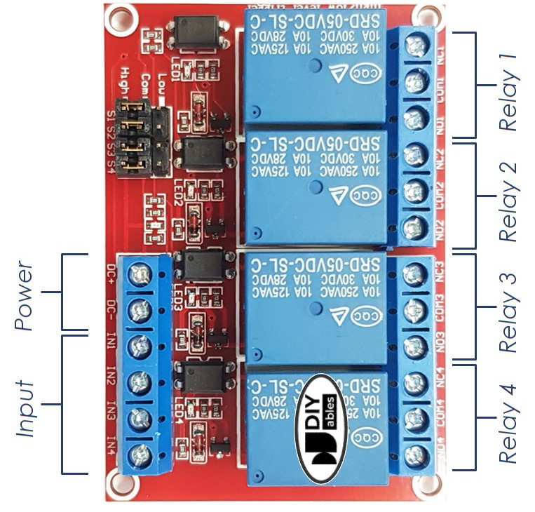 a. Relay Module PINOUT | 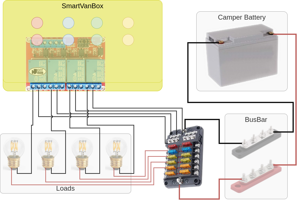 b. Load Connection Diagram for Relay Module |