Hardware - SVBox IoT 1.0
Assemble the SmartVanBox
Place the hardware in the SmartVanBox case, connect all components, and get ready to power up your new SmartVanBox.
Finally, we have all the components (hardware modules, case, and configured SD card) to assemble our SmartVanBox. Before inserting everything into the case, we need to connect some hardware modules.
Short Steps
- Power Supply:
- Solder UPS with DC/DC and jumpers.
- Prepare the internal Panel
- Attach IO Expander to Panel.
- Attach Relay module to Panel.
- Attach PowerIn connector (12V) to Panel.
- Wire IO Expander to Relay module on Panel.
- Cover and Buttons:
- Prepare IO Expander to Cover Buttons cable.
- Insert and secure buttons in Cover.
- Solder and join all positive button contacts.
- Solder negative button contacts with pull-down resistors.
- Solder jumpers to negative button contacts.
- Prepare connector for IO Expander in Cover.
- Assembly the SVBox:
- Position Battery and nuts for RPi Stack in Base.
- Insert Panel into Base.
- Position and secure UPS and DC/DC converter in Base.
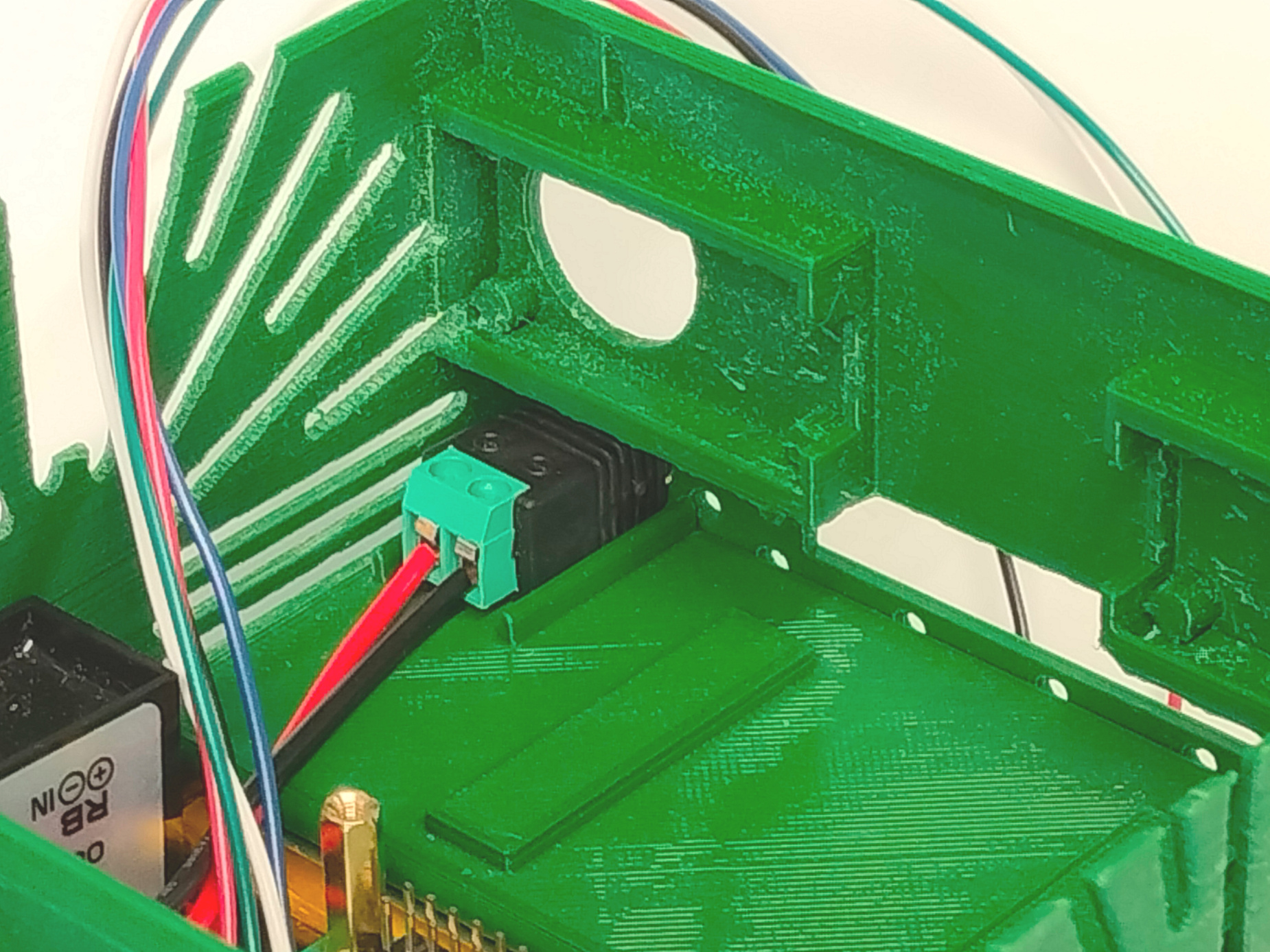
- Connect Battery to UPS and DC/DC to PowerIn connector (12V).
- Position and secure Raspberry Pi above UPS.
- Position and secure SIM7600 module above Raspberry Pi and attach antennas.
- Position and secure Sense HAT above SIM7600.
- Position and secure gas sensors.
- Connect modules to Raspberry Pi (UPS, GPIO Expander, and gas sensors).
- Final Assembly:
- Connect IO Expander to Cover Buttons cable.
- Power on the SmartVanBox.
- Place Cover on Base.
Power Supply
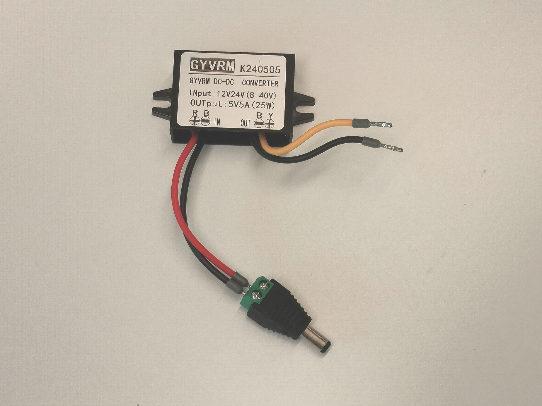
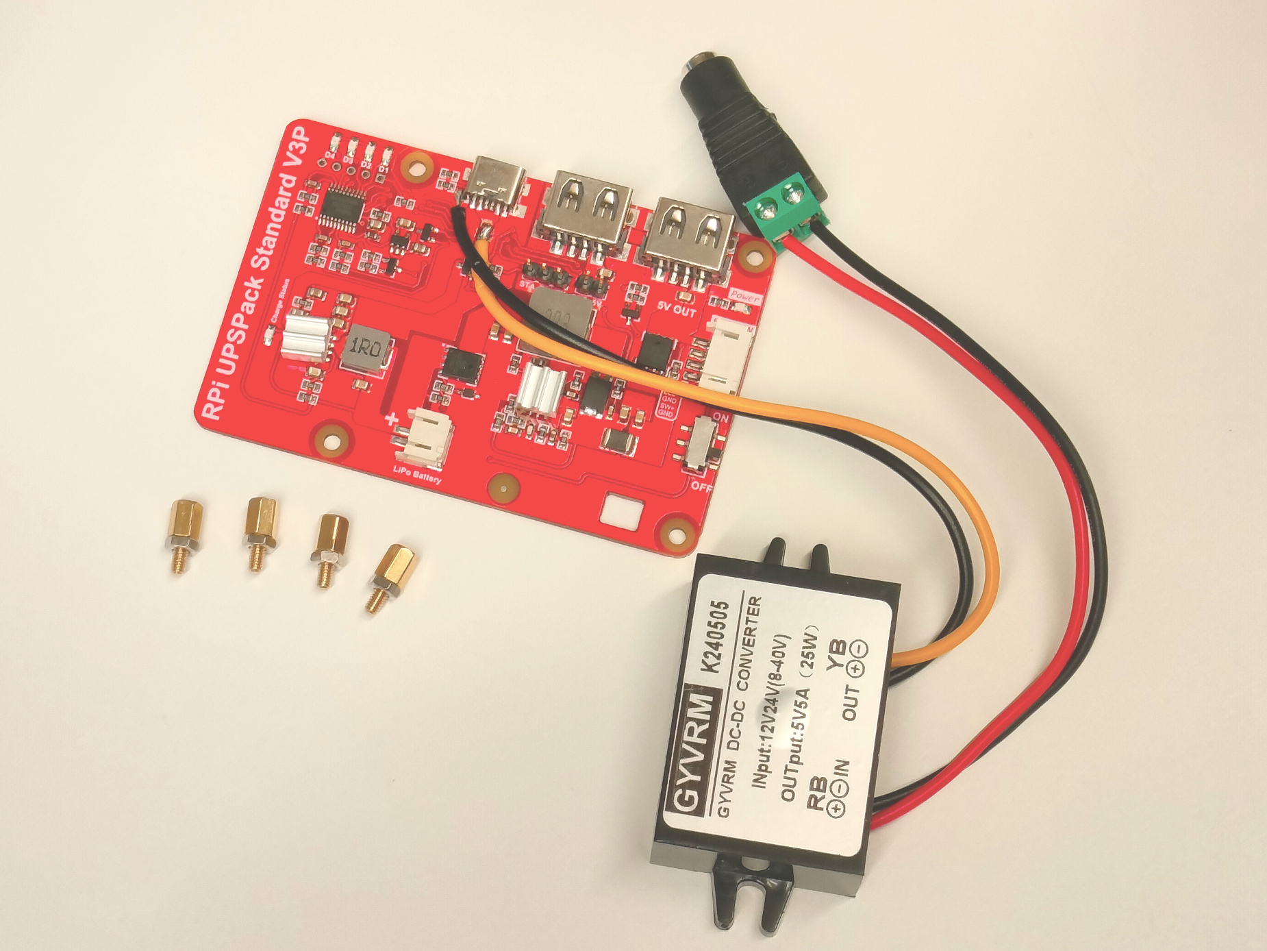
First, prepare the UPS module by connecting it to the DC/DC converter and jumper wires to the Raspberry Pi.
- Prepare DC/DC Converter Cables: The DC/DC converter has two pairs of cables, one for the 12/24V input and one for the 5V output. All four cables need to be stripped, and only the input cables should have crimp connectors0 attached.
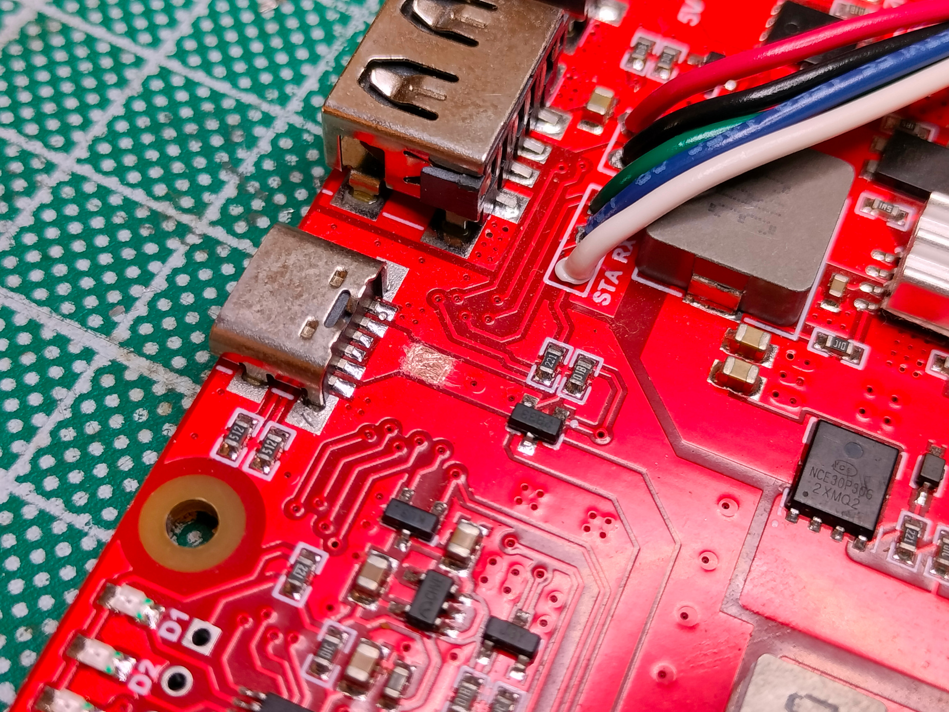
- Modify UPS Module: Solder the output cables from the DC/DC converter to the UPS module. You might need to scrape off some material from the tracks behind the USB-C port.
- Solder Jumpers to UPS Module: Solder jumper wires to the UPS module, behind the second USB port.
- Prepare Switch Button: take the self-locking button and prepare his cable with a 4 PIN's JST PH 2.0 port
|  2a. Prepare UPS Module |
 2b. Sold DC/DC to UPS | 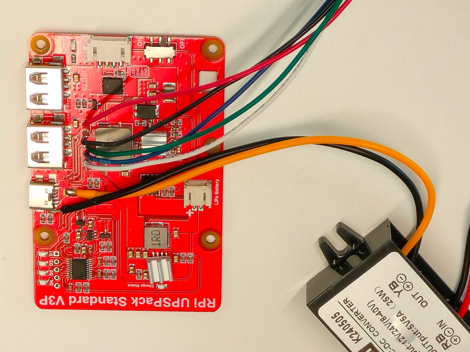
|
The Jumpers' order from bottom to top is:
| Color | Description |
|---|---|
| Red | 5V |
| Black | GND |
| Green | TX |
| Blue | RX |
| White | STA |
Prepare the Internal Panel
Now, prepare the previously printed panel and attach its components (GPIO Expander, Relay module, and PowerIn connector).
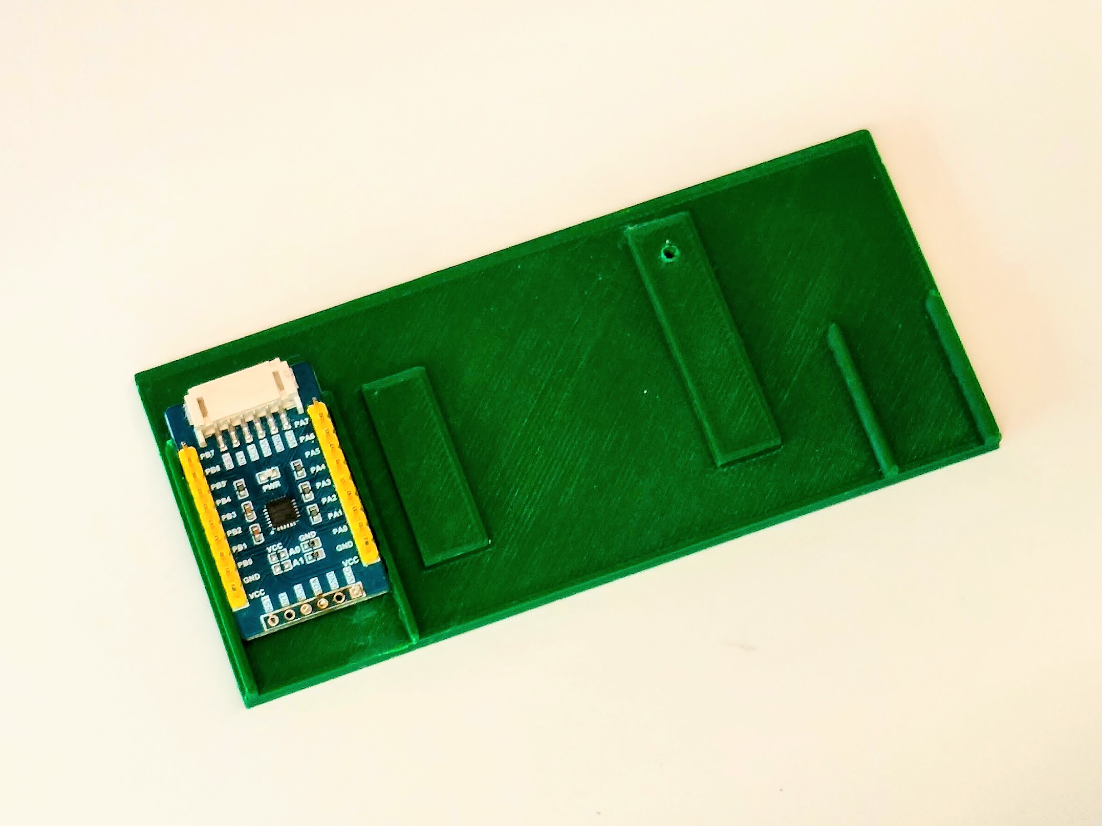
- Mount GPIO Expander: Secure the GPIO Expander module, using hot glue if necessary.
- Mount Relay Module: Secure the Relay module to the panel using screws.
- Position PowerIn Connector: Place the PowerIn connector in position.
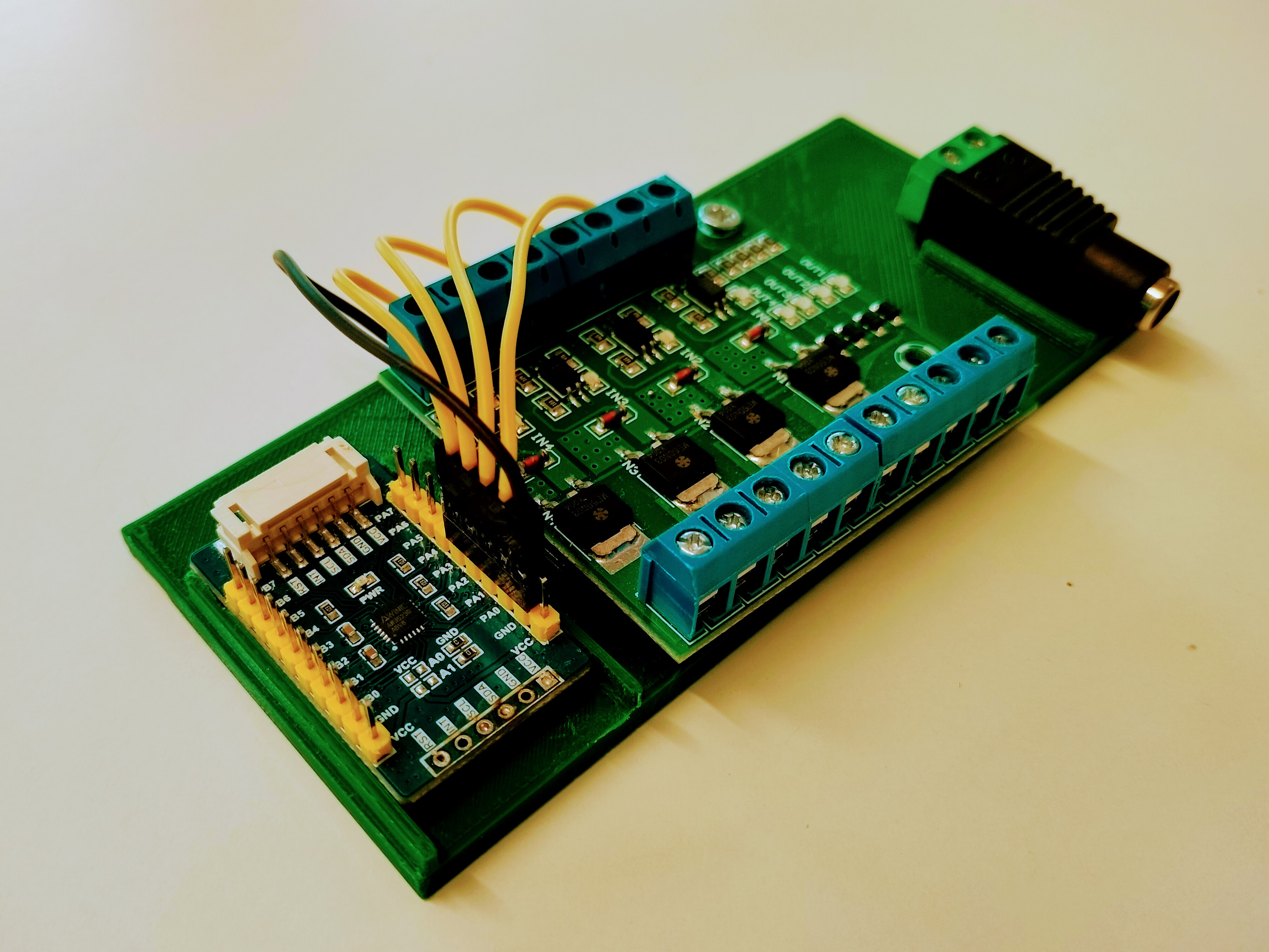
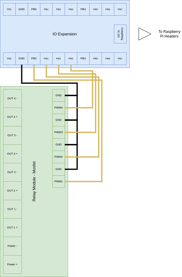
- Wire GPIO Expander to Relay Module: Connect the GND pins of the Relay module in a cascade manner, with the last GND pin also connected to the GPIO Expander GND pin. Connect the positive pins of the Relay module to the respective pins on the GPIO Expander, from P0 to P3.
Panel for Relays module

|  2a. Place the Relay Module |  2b. Fix the Relay Module |

|  4a. Connect GPIO Expander to Relay (GND) |  4b. Connect GPIO Expander to Relay (Positives) |

|
Below is the wiring diagram for connecting the GPIO Expander to the Relay module:
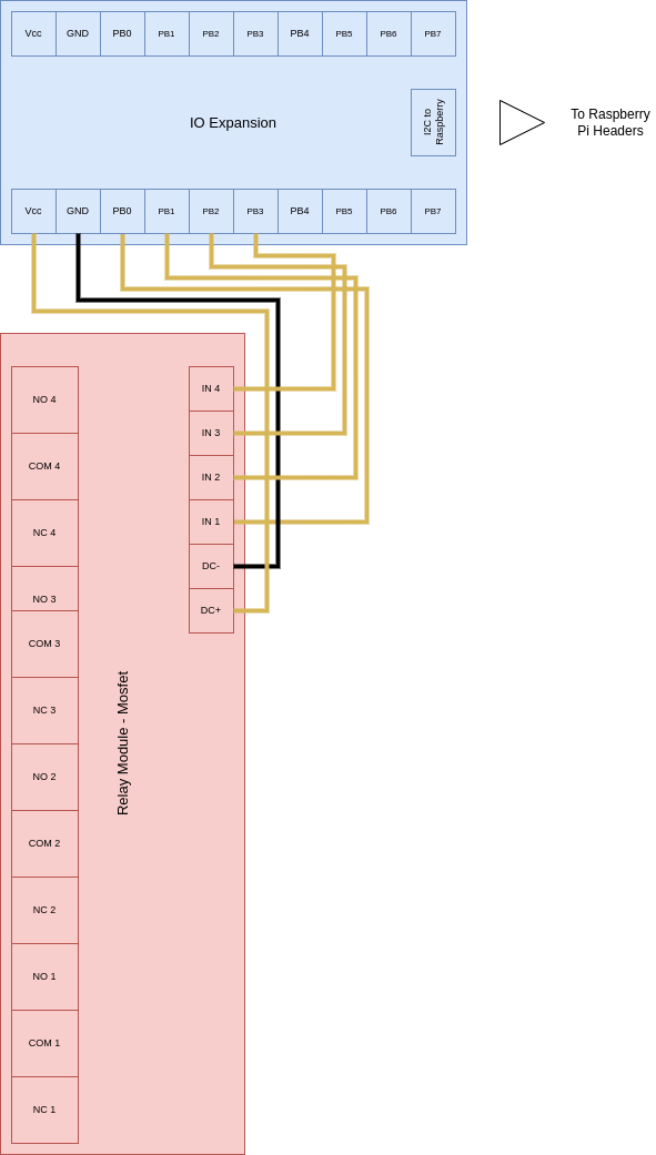
Panel for MOSFETs module
| 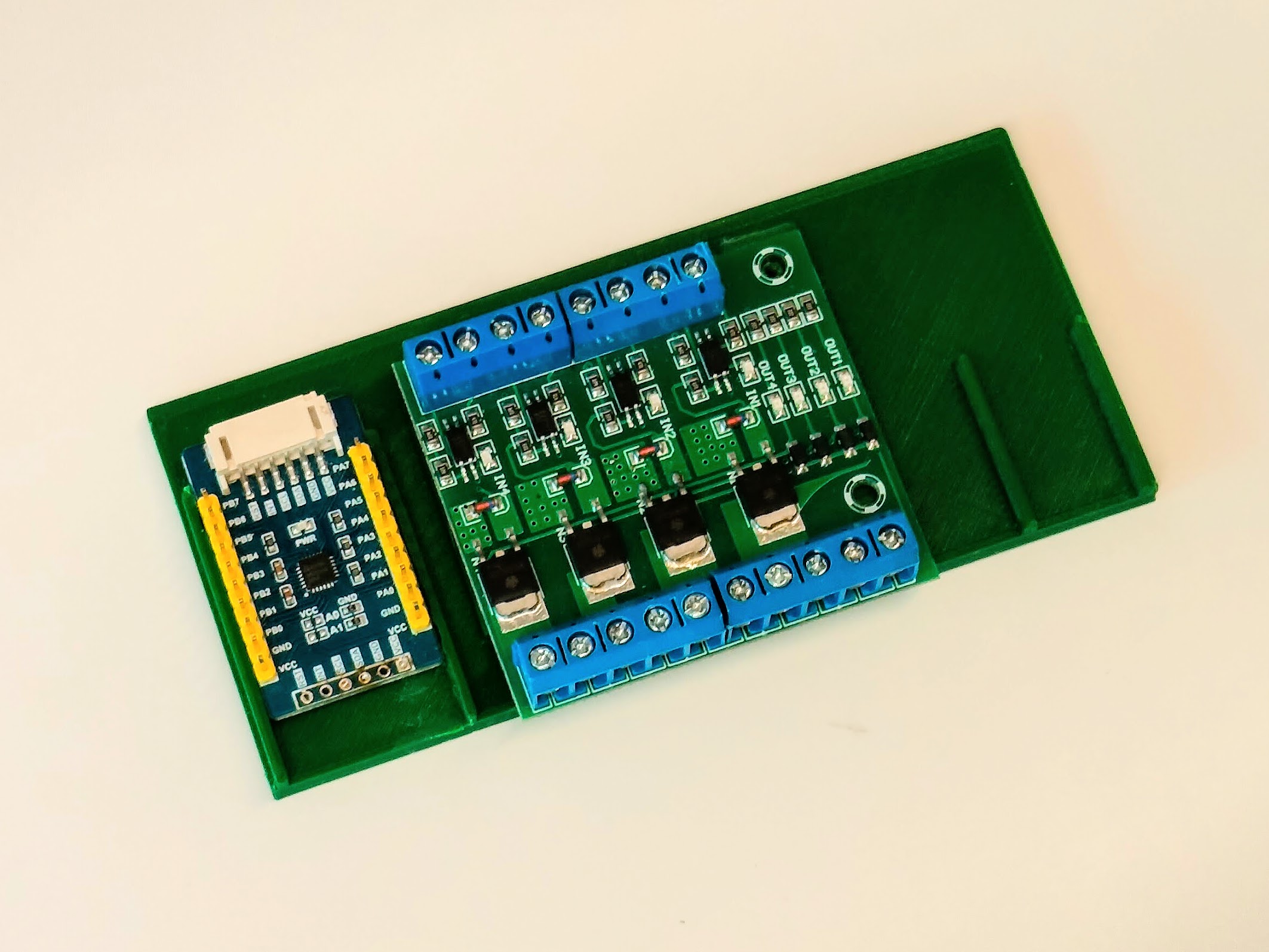 2a. Place the Relay Module | 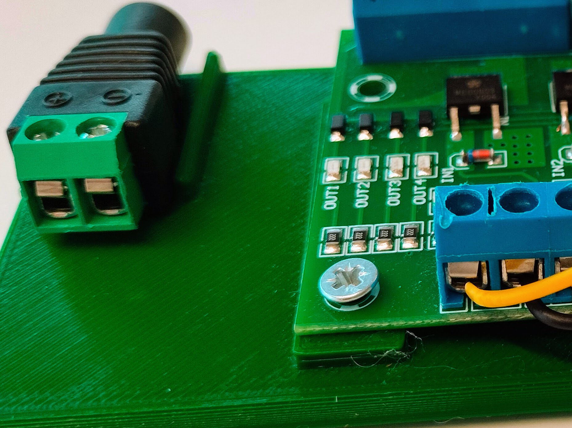 2b. Fix the Relay Module |
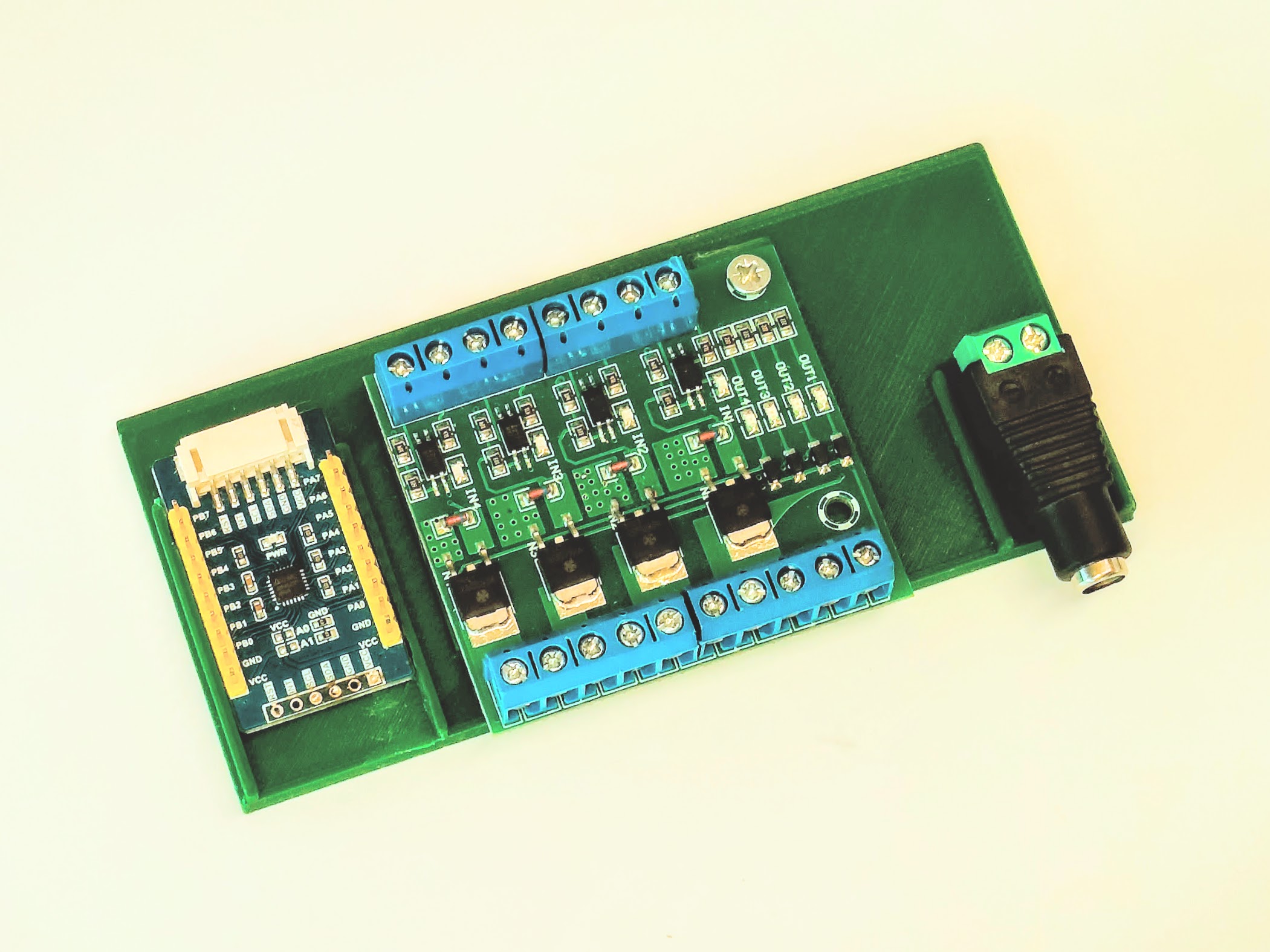
| 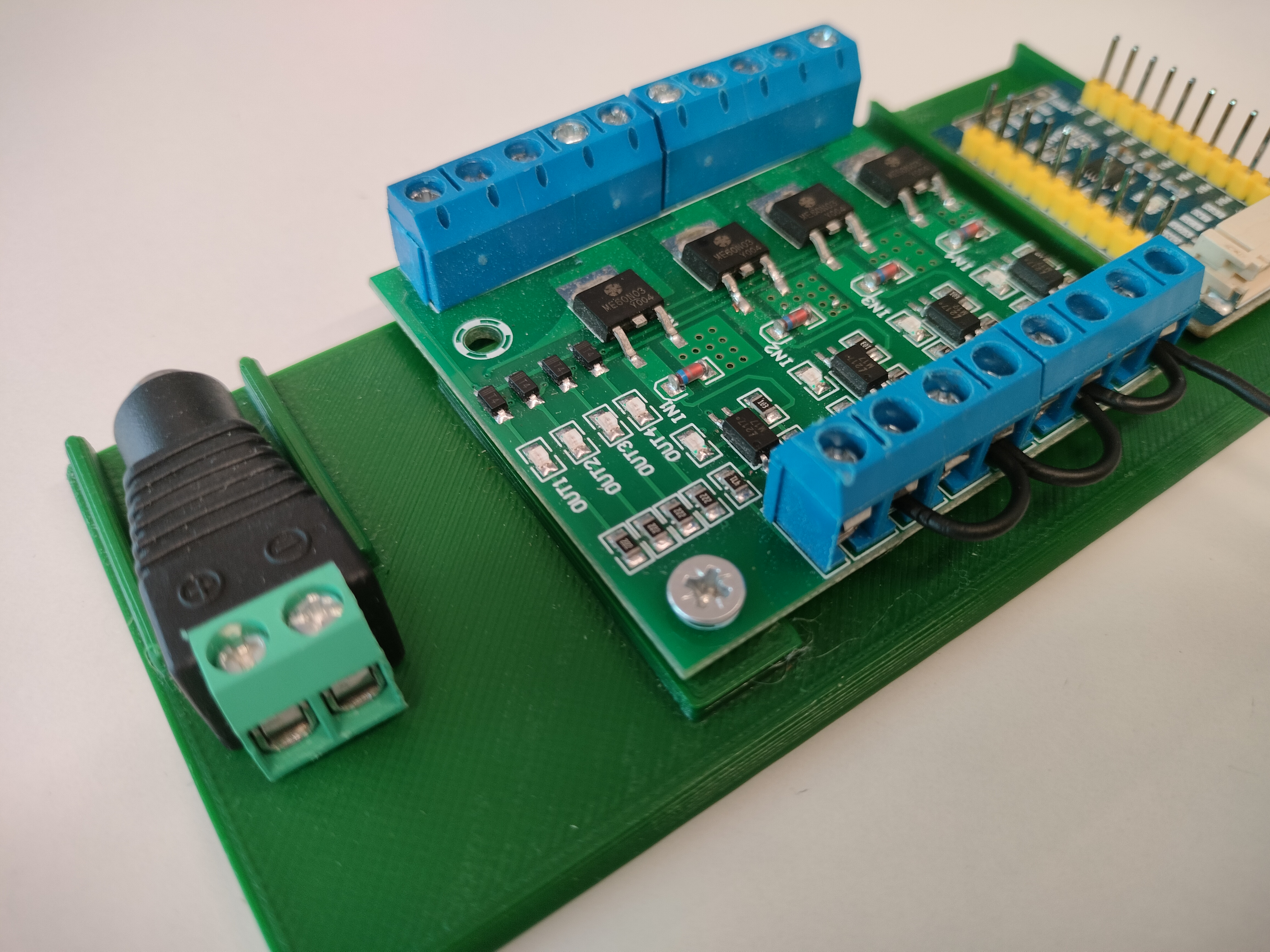 4a. Connect GPIO Expander to Relay (GND) | 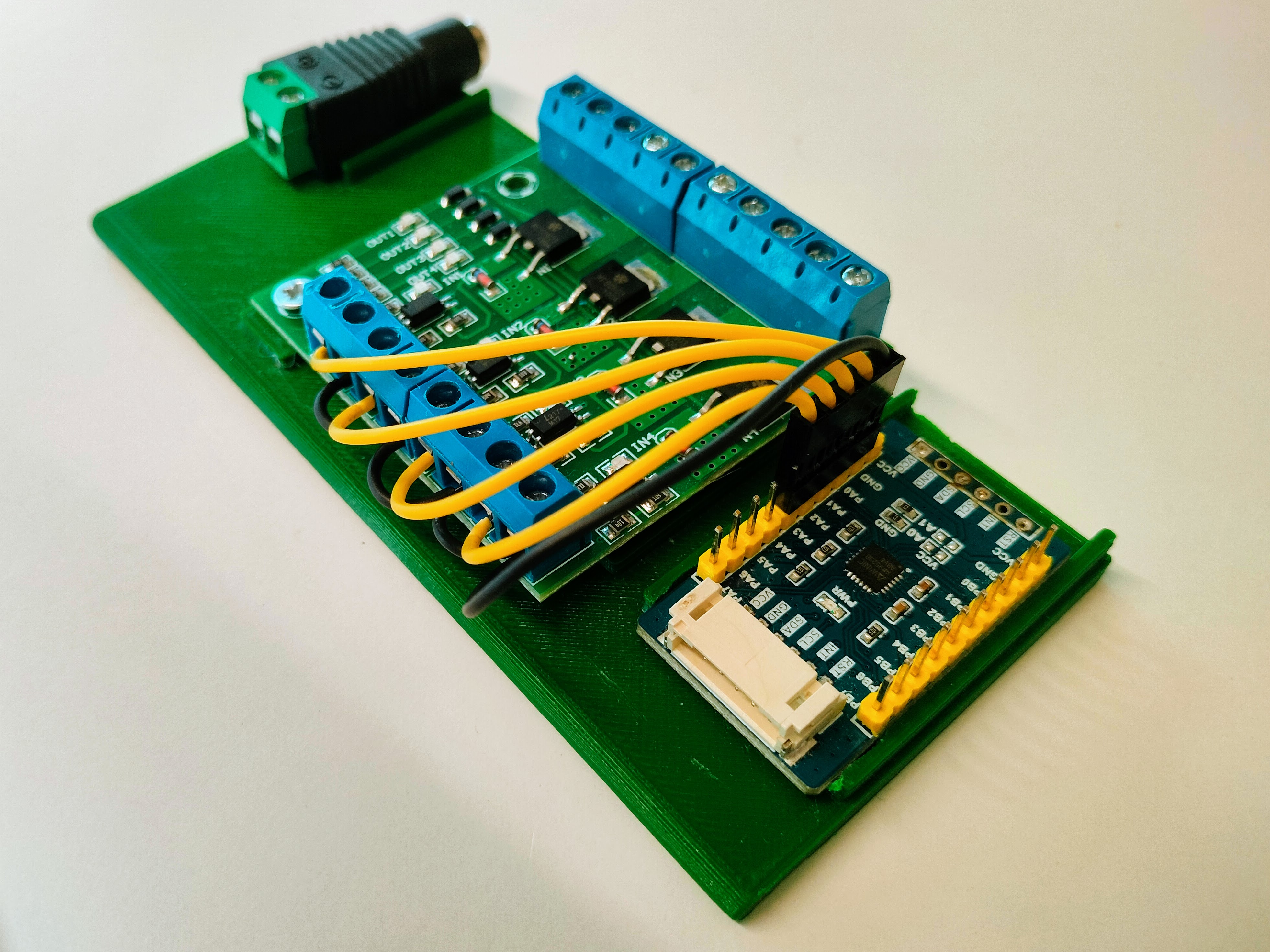 4b. Connect GPIO Expander to Relay (Positives) |
|
Below is the wiring diagram for connecting the GPIO Expander to the Relay module:
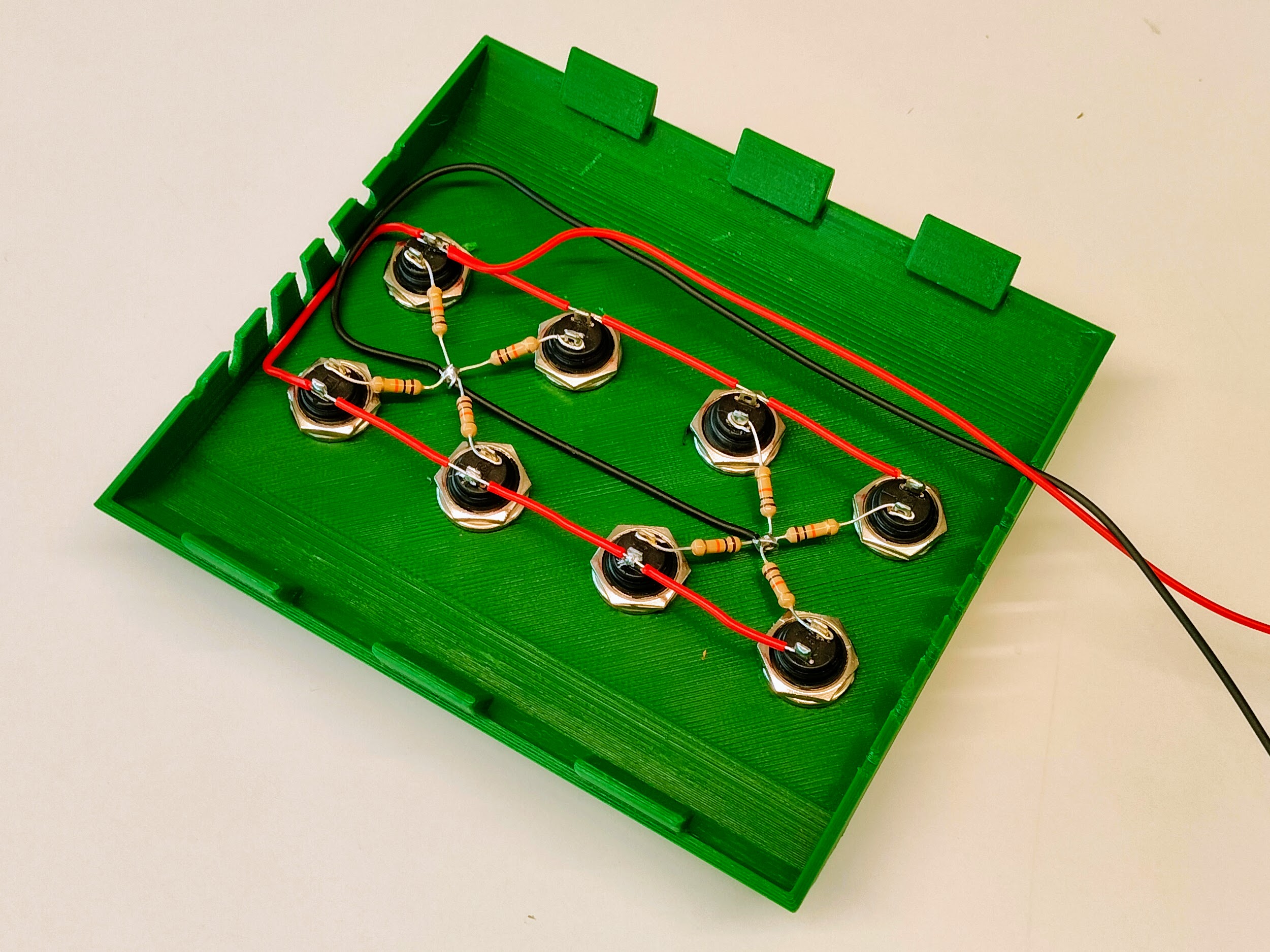
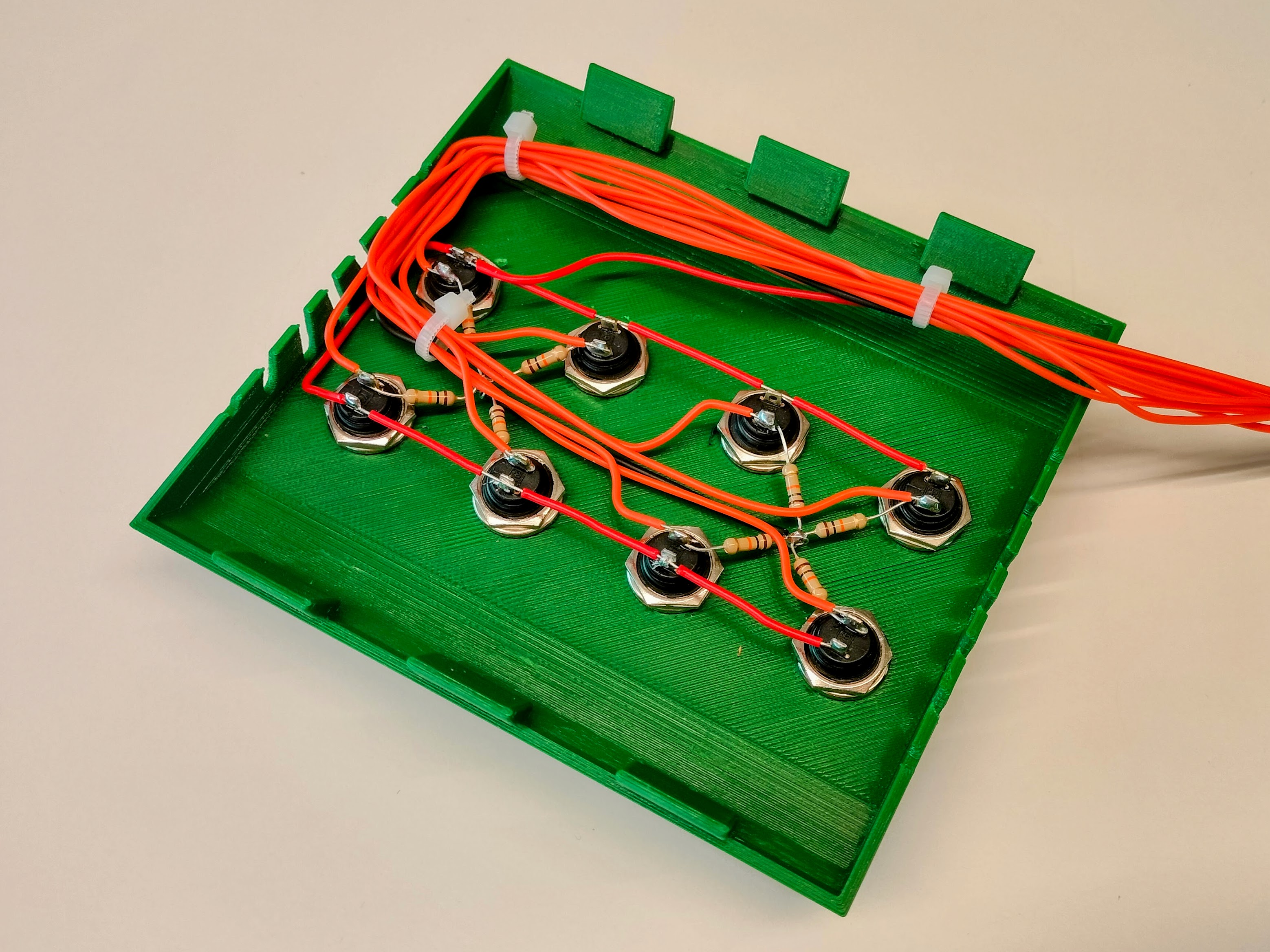
Cover and Buttons
- Install Buttons on Cover: Insert the buttons into the cover and secure them with nuts.
- Connect Positive Contacts: Connect all the positive contacts of the buttons together.
- Connect Negative Contacts with Resistors: Connect the negative contacts using 10kOhm pull-down resistors.
- Solder Jumper Wires: Solder jumper wires to the negative contacts.
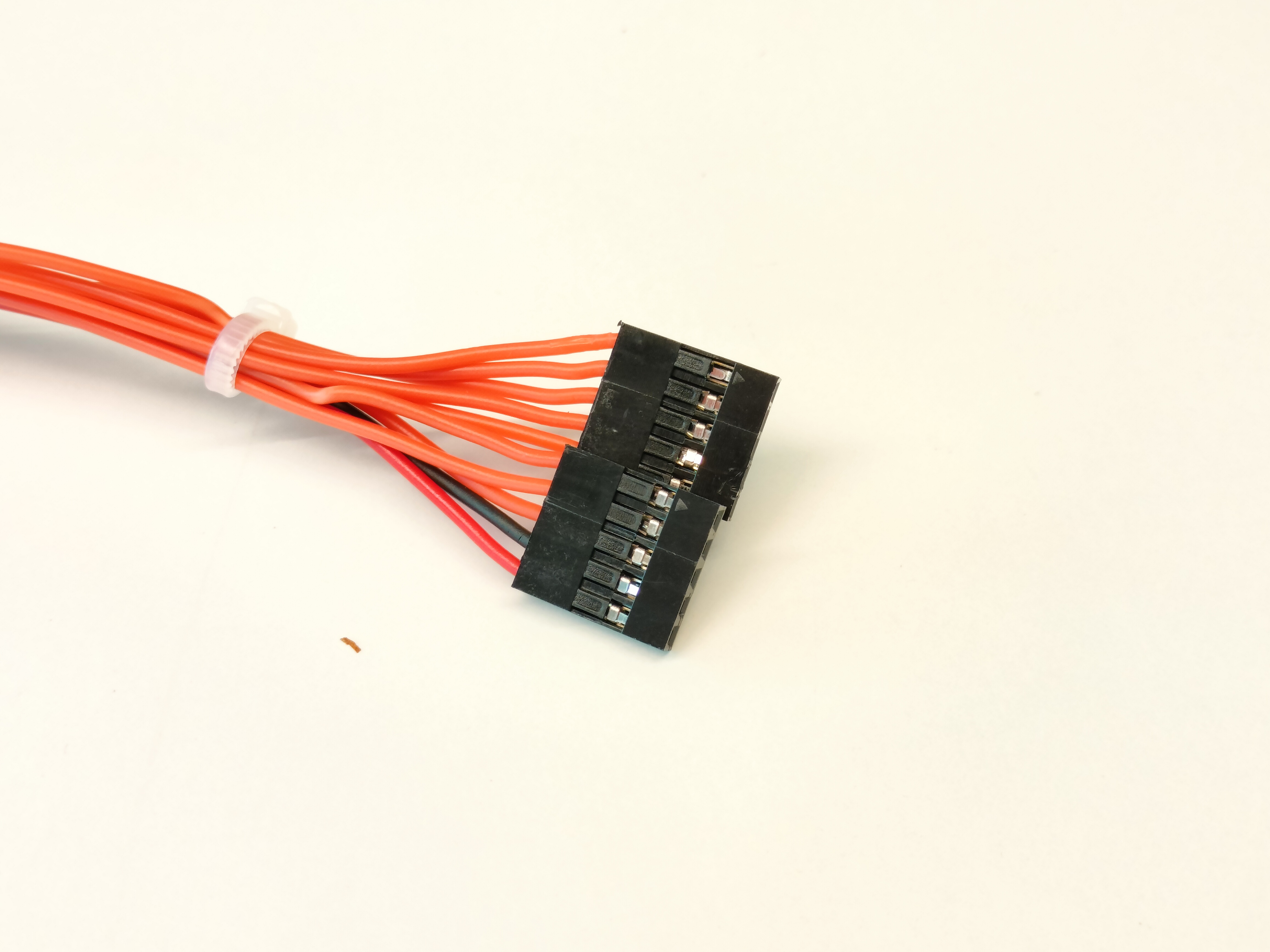
- Prepare Cover's Connector: Connect these jumpers, including negative and positive, to a female DouPont connector. You can use 2 connetors with 5 poles each one.
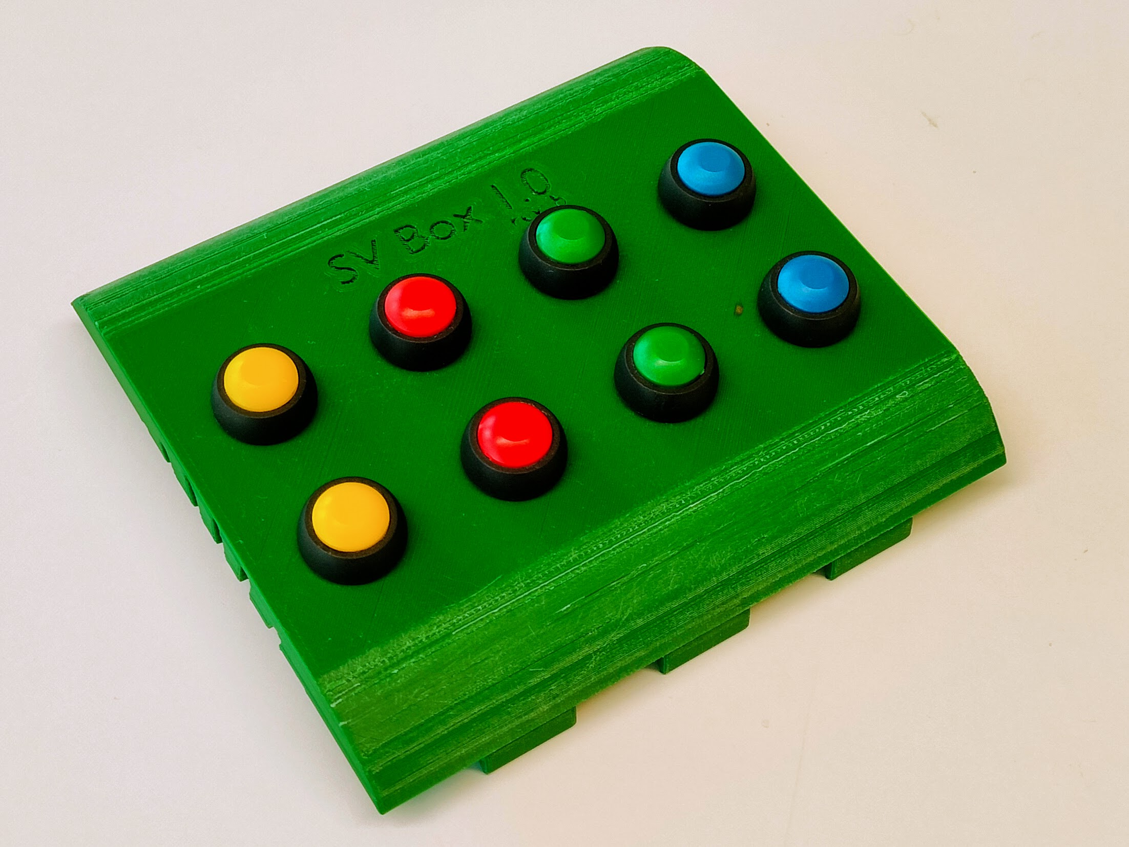
| 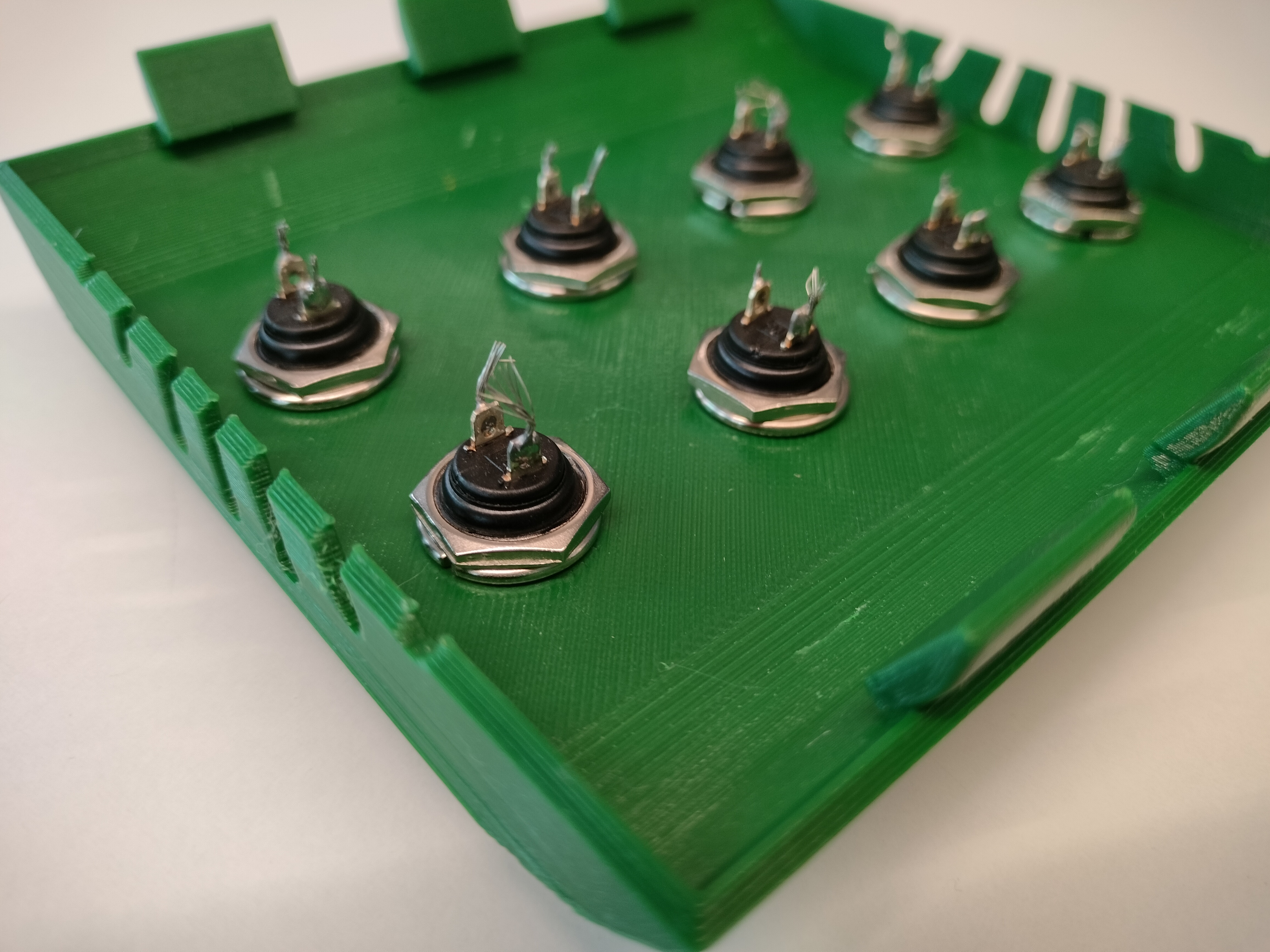 1b. Align all buttons | 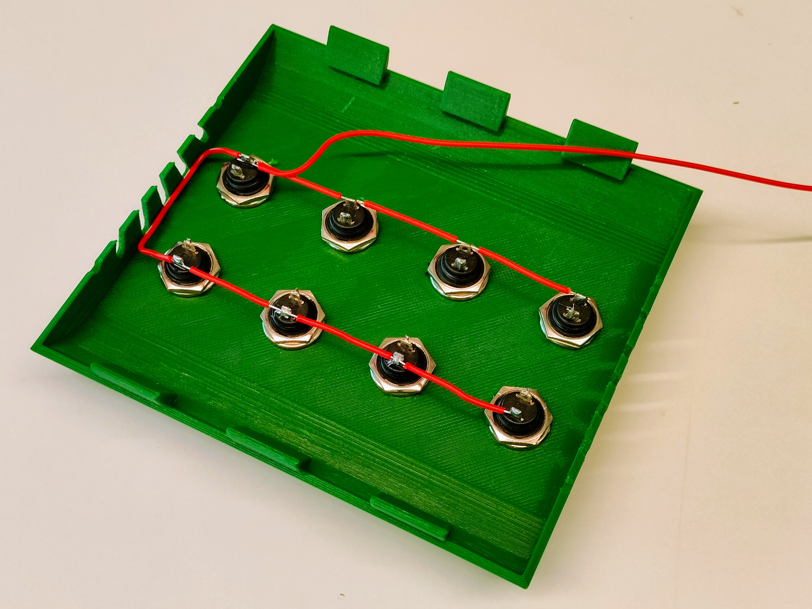
|
| 
| 
|
Connector 10 PIN
This connectoor will be attached to the GPIO Expander's inside the SVBox.
| VCC | GND | P0 | P1 | P2 | P3 | P4 | P5 | P6 | P7 |
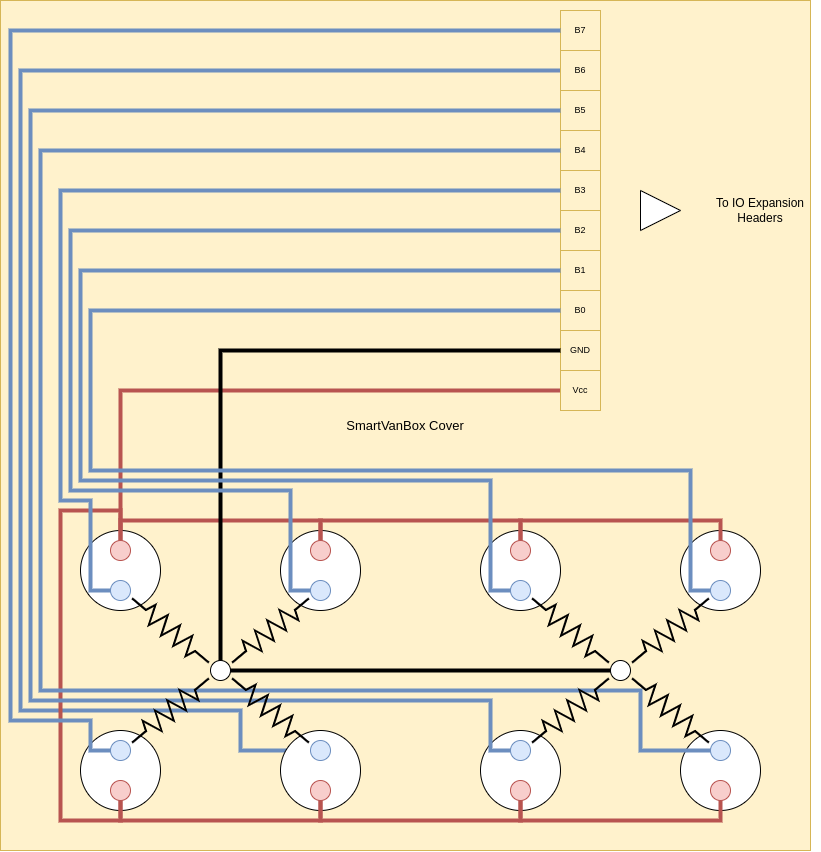
Below is the wiring diagram for connecting the Cover Buttons to the GPIO Expander's port:
Assembling the SmartVanBox
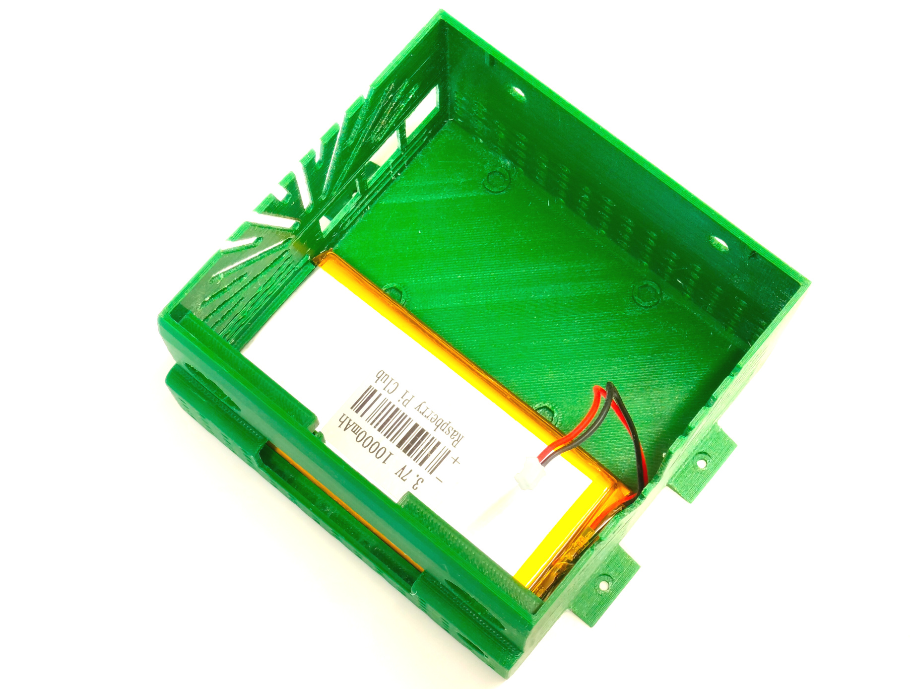
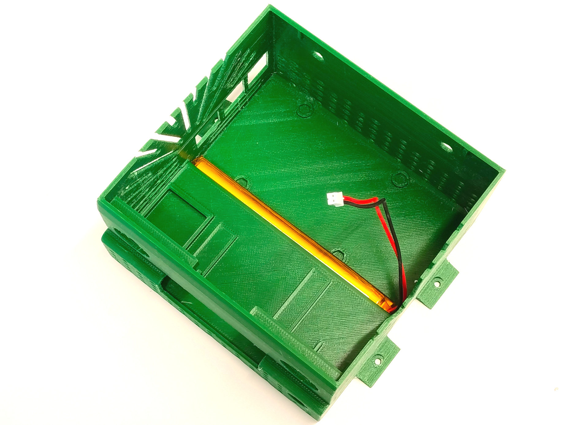
- Place the Battery: Insert the battery into the base.
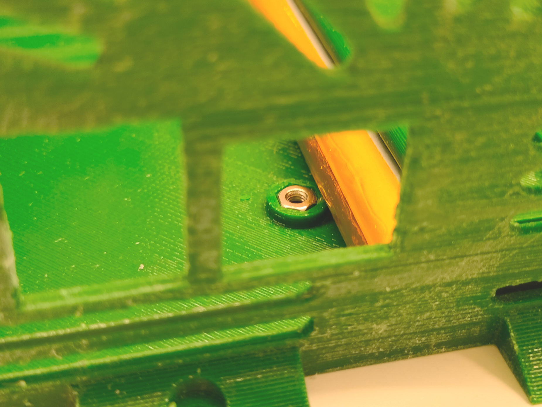
- Position the Nuts: Place the four nuts into their slots.
- Insert the Panel: Slide the panel into the slots above the battery.
- Install UPS Module: Position the UPS module with the USB ports facing the case and secure it with 6mm spacers. Position the DC/DC converter in the remaining space.
- Connect Power Cables: Connect the DC/DC converter input cables to the PowerIn connector and connect the battery to the UPS module.
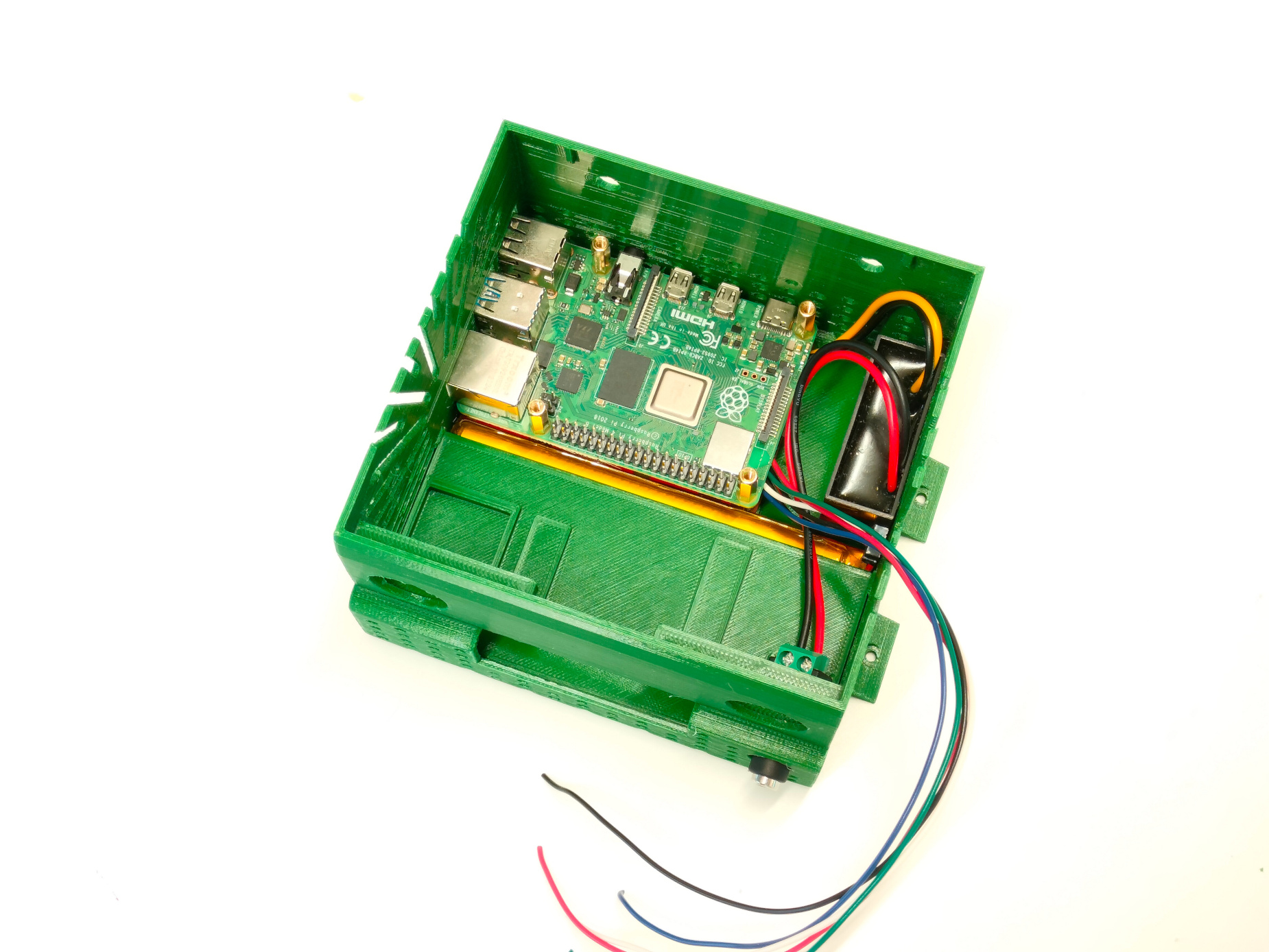
- Install Raspberry Pi: Place and secure the Raspberry Pi above the UPS module.
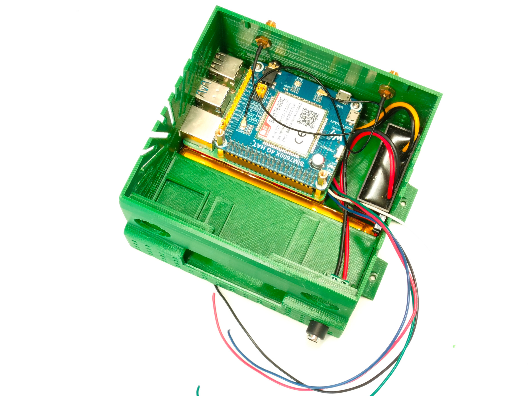
- Add SIM7600 Module: Position the SIM7600 module above the Raspberry Pi and attach the antennas.
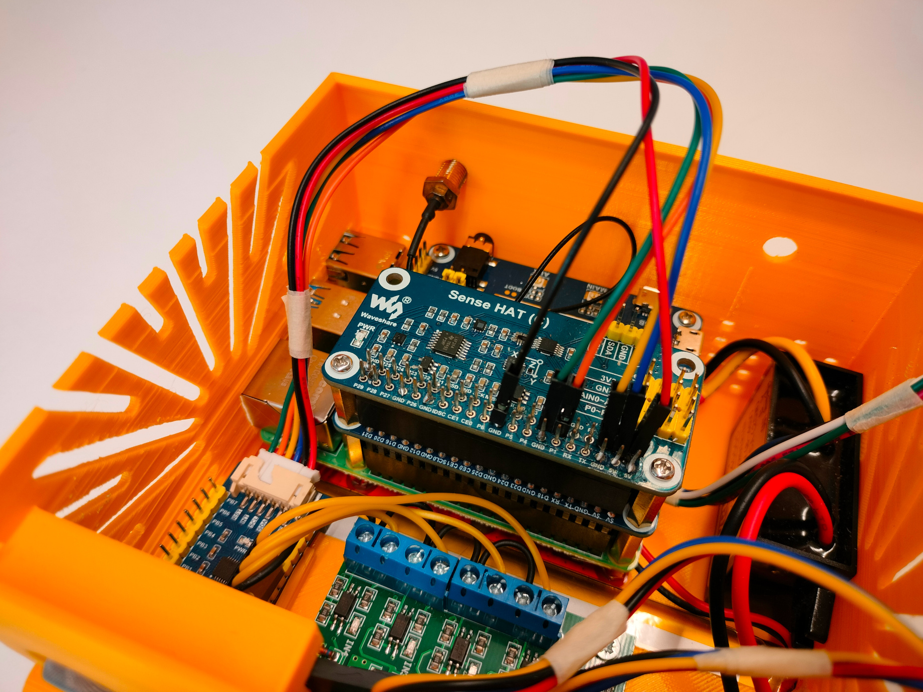
- Install Sense HAT: Position the Sense HAT above the SIM7600 module.
- Install Gas Sensors: Place the gas sensors into their slots.
- Insert SIM7600 Antennas: Attach the SIM7600 antennas to the module and insert them into the holes on the case.
- Place the Switch On/Off: Place and fix the switch button in the cover.
- Turn on the UPS: Turn on the UPS module using the switch placed on the board.
| 
| 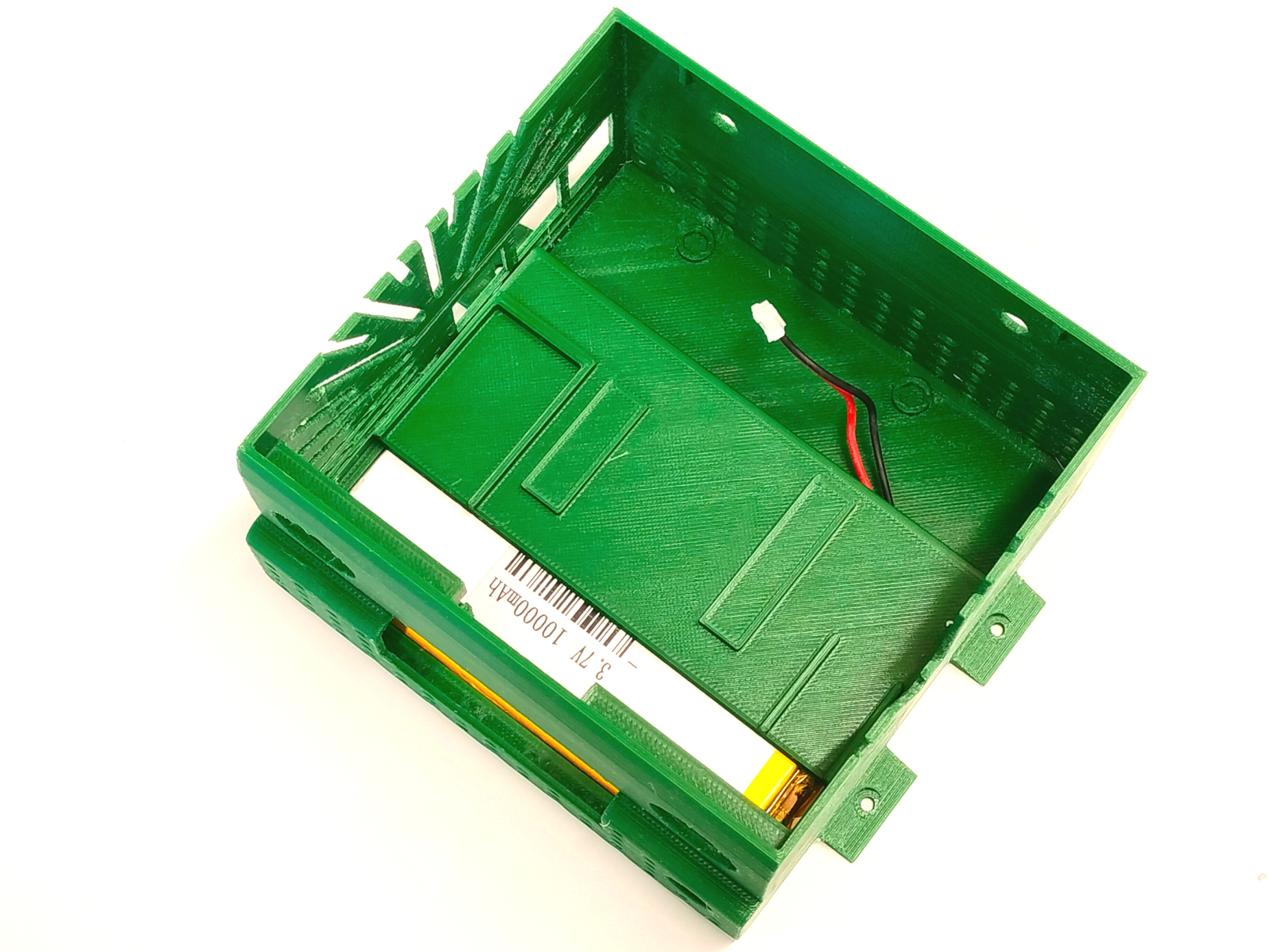 3a. Place the internal panel |
 3b. Slide the internal panel | 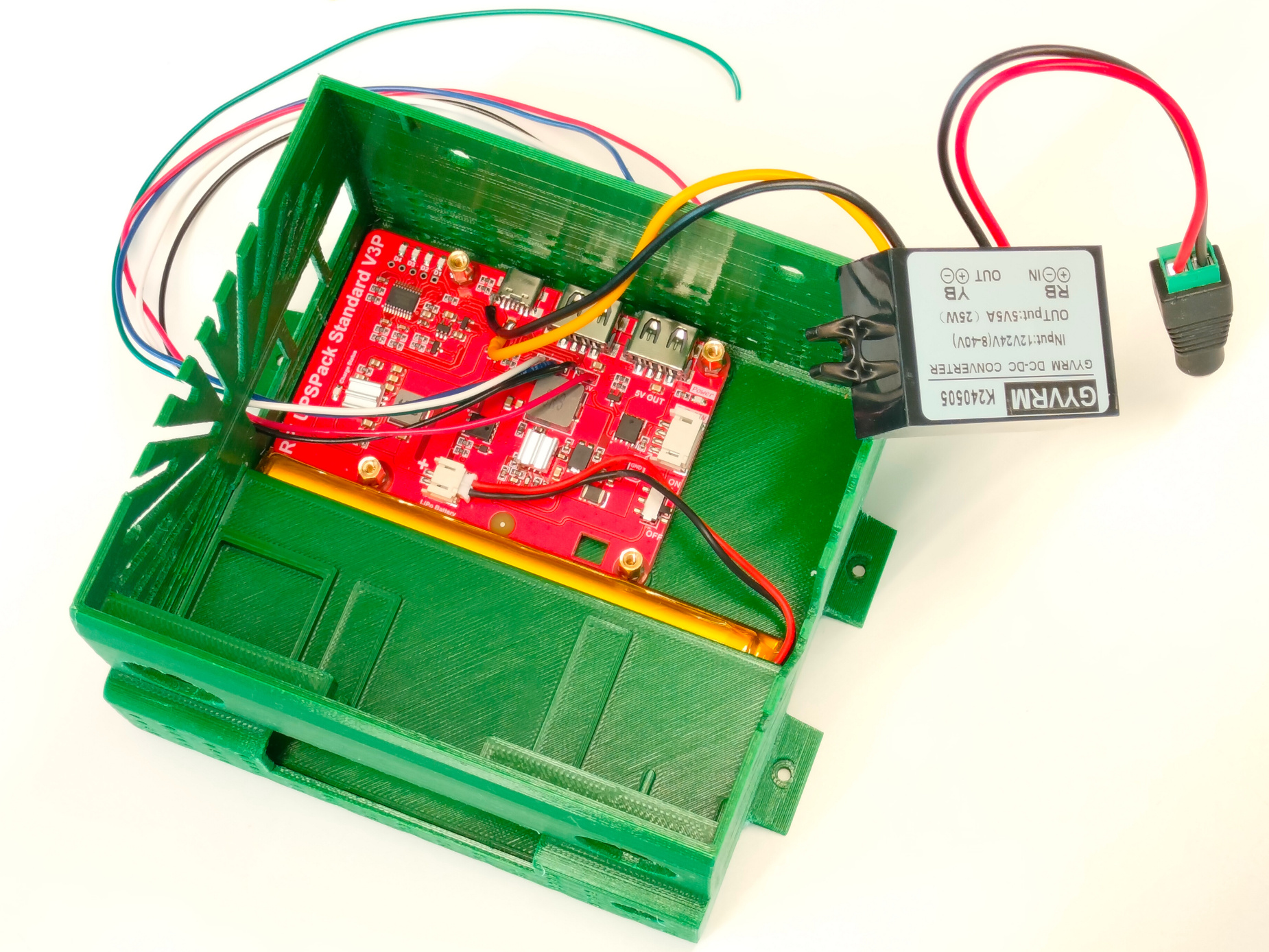
| 
|
| 
| 
|
| 
| 
|

|
Most of the components are now in place. It's time to connect them. Many of the necessary cables are provided with the hardware modules (GPIO Expander and Gas sensors). For the others (UPS), you need to prepare them using the DouPont connectors.
The UPS Pack V3 module to the Raspberry Pi's headers
| 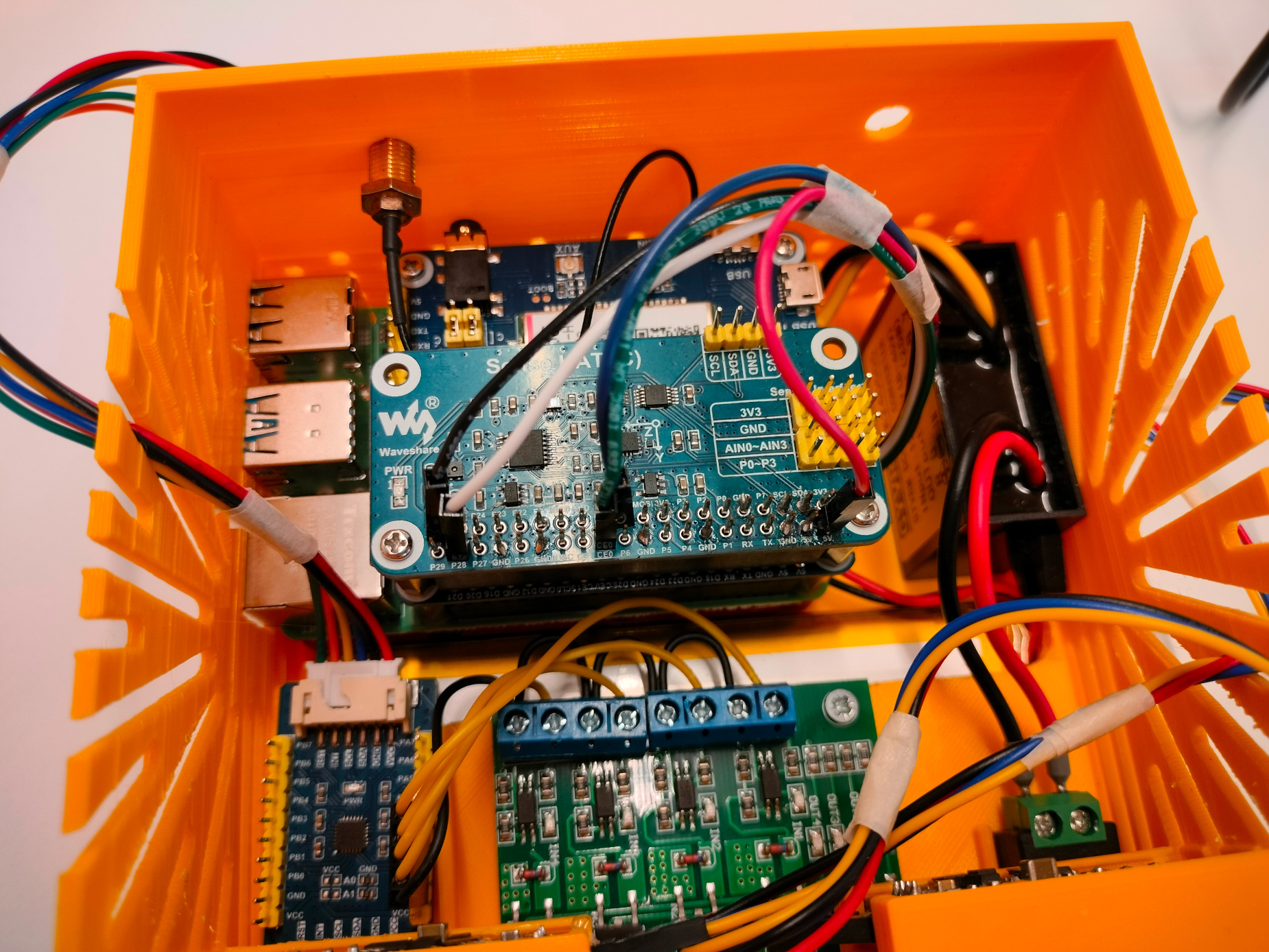 |
The GPIO Expander module to the Raspberry Pi's headers
|  |
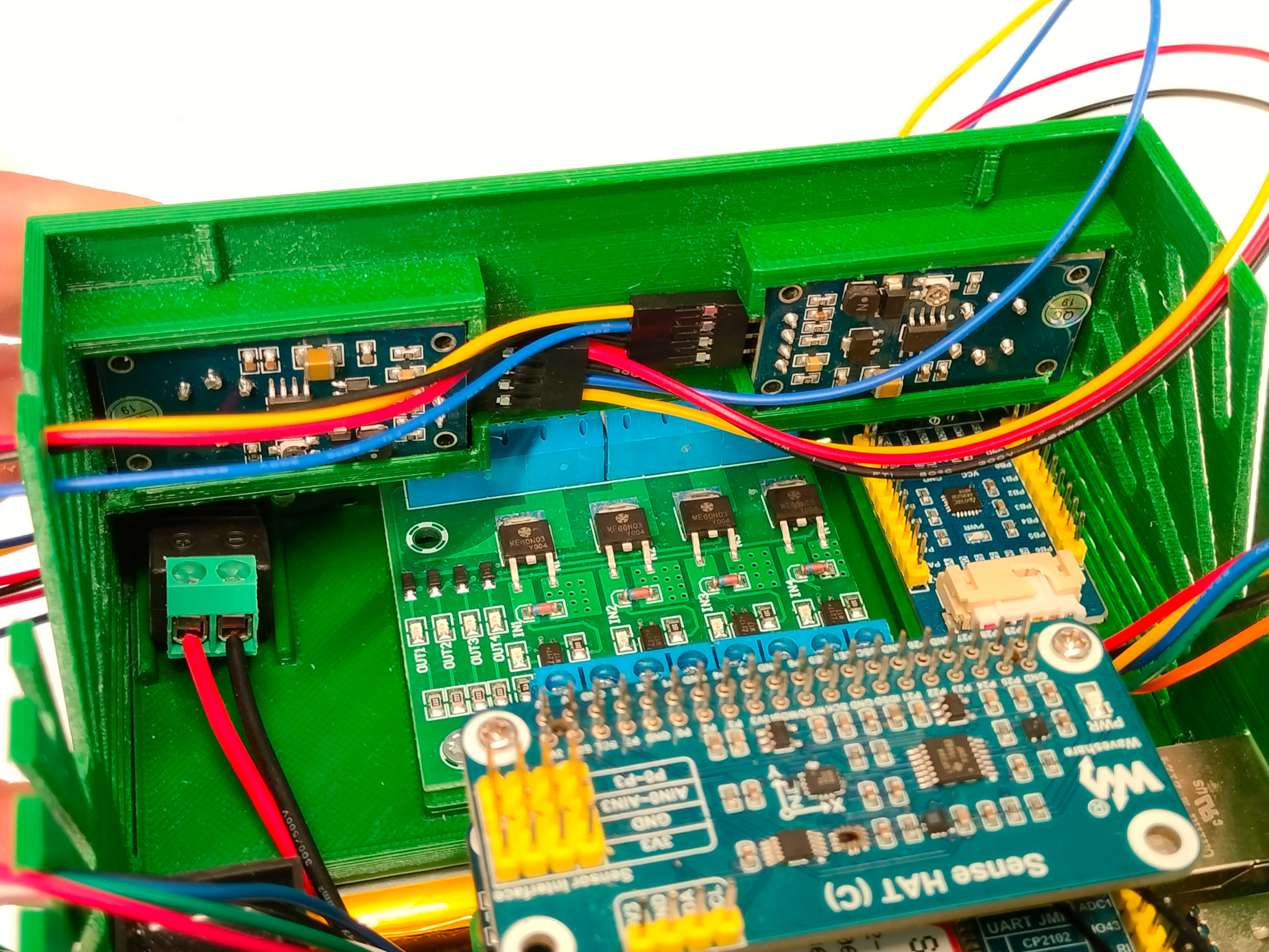
The Gas Sensors to the Sense Hat's analog headers
| 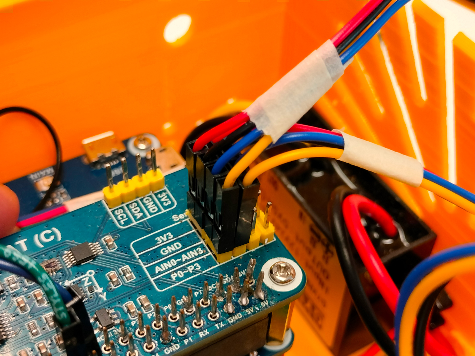 |
Below is the wiring diagram for connecting the Raspberry Pi headers to other modules:
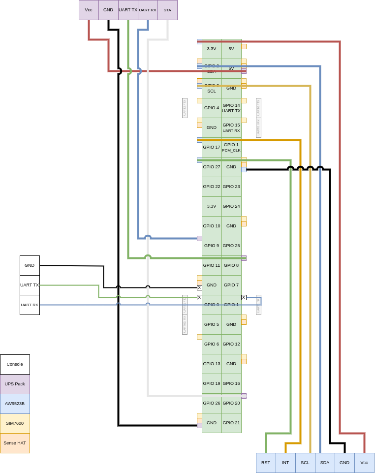
This diagram provides a clear guide on how to connect each module to the appropriate header pins on the Raspberry Pi, ensuring a seamless setup for your SmartVanBox.
Final Assembly
- Connect Cover to Base: Connect the cable extending from the cover to the GPIO Expander.
- Close the SmartVanBox: Insert one side of the cover first, then apply some pressure to insert the other side.
- Power On the SmartVanBox: Turn on the SmartVanBox using the On/Off switch.

| 
| 
|